<구글콘솔>


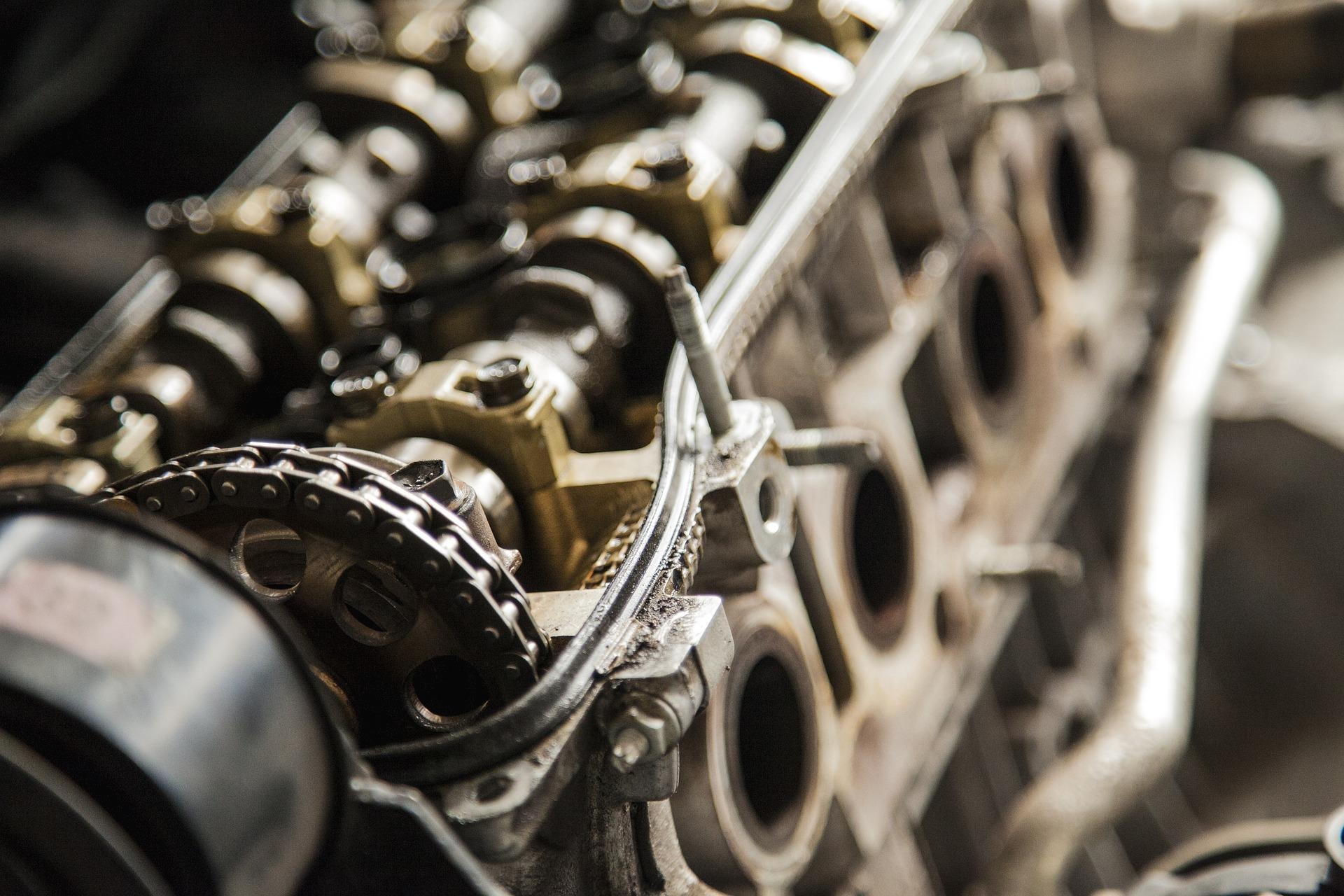
2019/04/10 - [자동차 & 선박 디젤 엔진 ] - INSTRUCTION MANUAL HEAVY DIESEL ENGINES!!


INSTRUCTION MANUAL HEAVY DIESEL ENGINES!!

Information sharing on diesel engines I am a Korean. Please understand even if I am not good at English. As I am interested in korea ship engines and korea car engines, I would like to share the inf..

ezexec2.tistory.com

Ship Engine Basic Configuration

The Diesel is designed as a high-speed, general-purpose diesel engine on the basis of our own research efforts, and has been delivered to many users both at home and abroad for its superb performance, durability, reliability and economy.


The engine is a vertical, single-acting, 4-stroke cycle diesel which is available in a series of models with or without a turbo blower.


The engine is used extensively as a marine main engine, marine auxiliary engine, factory main generator, emergency generator for buildings, and as a power plant for various industrial uses.


The engine body is a one-piece cast iron structure, which is designed to be sturdy and com-pact for high-speed operation. The engine is also designed for ease of handling, maintenance and inspection.


In addition, the engine has the following performance features.

(1) The engine is mass-produced so that the cylinder heads, cylinder liners, pistons, crankshaft, connecting rods and other major parts and valves of the same size are interchangeable.

(2) The major rotating parts of the engine are well balanced to minimize vibration and noise during engine operation. (3) The engine is direct injection type and starts easily even in the cold season.

(4) The Bosch type fuel injection pumps are simple in structure and easy to adjust.

(5) The engine is coupled as a marine auxiliary engine to a standard, single-bearing generator with a self-exciter into a compact marine generator under a technical tieup with a generator manufacturer, and is available in a series of models (CNS Series).

엔진단면도추가
엔진단면도


Engine construction

(1) Crankcase and oil pan

The crank room is formed by the cylinder column, which holds cylinder liner and the cylinder crankshaft, and the oil pan, both of which are assembled into one-piece construction. The crankshaft is held by so-called hunger type bearings in the cylinder culumn. The liner are so-called wet liners forming water jackets with the inner surface of the cylinder column to improve liner cooling.


The lower neck in the liner hole has two O-ring and square ring to separate the water jacket from the crankcase.

엔진오일팬
언더카바

ON the left side of the cylinder column is the intake and exhaust valve device which is connected to the camshaft via a bearing. In rear of the crankcase is the gear case which houses various gears, and may be connected the flywheel case where necessary.


On the top of the cylinder column there are six bolts for each cylinder for tightening the cylinder heads, and also special metal parts for feeding lubricating oil and cooling water to the cylinder heads. The oilpan is bolted to the bottom of the crankcase. Made of steel plates, the oil pan has the suction pipe for the main lubricating oil pump and the suction pipe for the standby lubricating oil pump which serves also as a lubricating oil drain pipe inside. The pipe ends are fitted with a suction filter.


(2) Cylinder heads

The cylinder heads are a one-piece, single cylinder type. They are mounted with copper ring gaskets on the cylinder column by means of 6 bolts each, and form the main combustion chambers with the top of each piston. The cylinder head is provided with two intake valves and two exhaust valves, a fuel injection valve, etc.


The intake and exhaust valves are made of special heat-resistant steel, and are reinforced with a layer of stellite where they come into contact with the valve seats and rocker arms. The cylinder heads use valve seats of special-steel. and exhaust valves have valve rotators which automatically rotate the valves as the valves are opened and closed.


cylinderhead
엔진해드

This provides sufficient valve durability against gas blowout.


The inside of the cylinder head is lubricated by a forced lubricating system which feeds lubricating oil through a special metal part. The cylinder head is totally enclosed inside.

A decompression plug which is used in engine turning, etc. is provided on the cylinder head side.


(3) Pistons and connecting rods

The pistons and are made of special cast iron or cast F.C.D depending on what purpose the engine will be used for. Each piston has three compression rings and one oil ring. The top compression ring is chromed and this reduces wear considerably.

The oil ring is a so-called coil expander ring having a built-in coil spring for added tension. The pistions are connected. to the connecting rods with piston pins

piston-rod
piston&rod

The connecting rods are made of especially tough steel, forged to have an I-shaped cross section. No drill hole is made in the connecting rod to maintain the durability of the crank pin metal. The small end bushing is splash lubricated by jet cooling.

The connecting rods are connected to the crankshaft at their large end. The large end, which consists of two parts, is assembled with two cap bolts.


The bearings are made of thin 3-Layer metal to assure sufficient durability against large loads. The large end is an important part, which is one of three internal engine parts that are often disassembled.


For this reason the bolts must be torqued to the specified value. As mentioned before, these cap bolts are important and will often have to be removed so that care must be exercised when disassembling and assembling the large ends of the connecting rods. The bolts are punched with match marks for location identification. The cap bolts must be replaced with new ones after a specific period of use like some other parts.


(4) Crankshaft

The crankshft is a one-piece die-forged shaft or a free-forged shaft with 8 balance weight of special steel.

crannkshaft
crank shaft

The crank journals and pins are carburized and precision-finished by grinding the outside surfaces. The crankshaft is well balanced to eliminate harmful vibrations at high speed.

The crank journals carry 3-layer (kelmet-metal) thin bearings. This and the hardened journals of the crankshaft assure ample strength against great loads. The bearings are complete units so that they can be easily replaced and offer sufficient accuracy.


The output end of the crankshaft is fitted with the flywheel and starting ring gear. Where necessary, a mass plate or a silicon damper is attached to that end of the crankshaft.


(5) Gear Train

The gear train is housed in a crankcase on the output end of the engine, and drives the camshaft, fuel injection pump, lubricating oil pump and cooling water pump.

geartarin
gear

The intermediate gears for driving the camshaft, fuel injection pump, etc. must be accurately timed so that each of these gears is punched with match marks on its teeth.

All the gears are made of carefully selected materials and their teeth appropriately shaped and treated to assure ample strength at high-speed, large-load operation and to minimize noise. The gear carries various devices on the outside.


(6) Starting system

The standard starting system for this engine is an air motor starting system using com-pressed air or a electrical starting system using sell-motor.

startinmotor
starting

The air motor is started by low-pressure air of 12 kg/cm2 which is fed through a quick valve to drive the vane type air motor, which drives the ring gear on the crankshaft via a pinion to start the engine.

The system has been favorably accepted by many customers for many features which include simpler construction than that of other systems and easy maintenance and inspection.


(7) Fuel control device

The fuel control device is located on the right side of crankcase. The engine can be idled or run at the rated speed. with a single handle. A fine adjustment of the rated speed can also be made easily.

Depending on customer specifications, a fine adjustment of the engine speed can be made with a motor by remote control.

The stop handle is located close to the engine speed adjusting lever. The starting handle is arranged compactly in a single place for easy handling.


(8) Fuel oil system

The fuel oil system includes filters, feed pump, fuel injection pump, fuel injection piping, nozzle holders, nozzles, etc. Two kinds of filters are used. The first filter is an auto-clean type, which removes relatively large foreign particles from the fuel oil, and can be cleaned without disassembling even when the engine is running.


The second filter (for regularly used engines only) is a wire type consisting of two filters, one of which may be opened for cleaning while the engine is running. The second filter removes fine foreign particles.


The feed pump is built inside the fuel injection pump. It is a plunger type pump driven by the camshaft which runs through the fuel injection pump. Even when the engine is not running, the plunger can be manually moved for making various kinds of checks on the fuel oil system.


(9) Fuel injection pump, nozzles and governor

The fuel injection pump is a Boech 6-cylinder one-piece type, to which the governor and feed pump are directly connected.

injection
f,o

The fuel injection pump is installed on the right side of the engine ) as viewed from the front of the engine), and driven from the the plungers in the firing order of the cylinders to generate high-pressure fuel oil. Fuel oil quantity can be uniformly changed automatically by turning the plungers with the rack.


A fuel injection valve is of automatic type and has such a construction as possible to be adjusted to the specified injection pressure with a spring, providing the best injection of fuel and perfect combustion is assured with whatever load you may operate the engine.

governo-parts
governor

The governor is a centrifugal governor which is directly mounted on the fuel injection pump, and has a control lever for engine speed control and a stop lever for stopping the engine.. The governor shaft, whose speed is increased by a gear on the camshaft of the fuel injection pump, has governor weights; the rack is automatically adjusted by the balance between governor springs and the centrifugal force of the governor weights to maintain uniform engine speed.


(10) Lubricating oil system

The lubricating oil in the oil pan is pumped up by the main lubricating oil pump via the strainer in the oil pan, running through the oil cooler and lubricating oil filter into the main pipe, which is cast into the crankcase, to lubricate various parts of the engine, and then returning to the oil pan. It is a forced lubricating system.


The internal working parts have drilled holes for letting the lubricating oil flow. The lubricating oil pump is a gear pump which is mounted to the gear case and driven by the drive gear.


The discharged lubricating oil is regulated to the correct pressure by the pressure regulating valve mounted on the blaket for the lubricating oil filter. The lubricating oil filter is a twin, notch-wire type. Installed on the right side of the crankcase. any one of the twin filters can be removed for cleaning by turning the changeover-cock-even when the engine is running. The lubricating oil cooler (shell tube type) has excellent cooling performance.


(11) Cooling water system

Cooling water pump The cooling water system is the fresh water secondary cooling system. The cooling water pump is directly mounted to the gear case and is driven with a gear.


The fresh water pump is a centrifugal pump Oil seals are used for preventing oil leakage. Mechanical seals are used for completely preventing water leakage and for preventing damage to the shaft. The fresh water discharged out of the fresh water pump enters the crankcase and flow through the cylinder jacket, cylinder head and water-cooled exhaust pipes before entry to the fresh water cooler. The fresh water then passes through the passage in the crankcase and is led to the fresh water pump.


• Seawater pump

A Wesco pump is used. This pump is divided into a vacuum chamber and a pressure chamber, and pressure chamber is equipped with an external casing which also functions as an air-water separation chamber. When the engine is started with priming sufficiently made through the external casing, water containing air bubbles is fed to the separation chamber from the pump casing because of revolution of the impeller. The air is discharged to the exterior of the pump barrel from the separation chamber and water only is delivered to the impeller from the separation chamber. This cycle is repeated and the automatic exhaust valve or the delivery port and pumping is finally performed. Even when running of the pump is suspended, water that is required for the self-priming action for the next running will remain in the casing. At the next time and subsequent. Therefore, the pump operates in a manner that is equal to that of a usual centrifugal pump.

seawater-pump-parts
swpump


Fresh water cooler

The fresh water cooler is located on the rear face of the crankcase.

The fresh water cooler is of tube type and incorporates an expansion tank chamber in the upeer part and a thermostat on a side face. The topmost part of the fresh water cooler is equipped with a pressure control valve (also used as the cap for replenishment of fresh water) and the fresh water temperature is controlled in the range of 65~76℃ by means of the thermostat. Be sure to check the fresh water level by observing the water level gauge or with the pressure control valve cap removed before start of operation. If the water level is low, replenish fresh water up to the level of the cap seal. The side cover contains zinc for corrosion protection. Inspect it from time to time. Draining of the fresh water will be smooth if that cap is removed. When the fresh water is drained while it is hot, steam may jet out when the pressure control valve cap is removed. Cover up the filler port with rag or other suitable means in such a case.

fresh-water-pump-parts
f.wpump


거버너(GOVERNOR)의 구조 및 기능

디젤 엔진에서는 최고 회전을 제어하고 엔진에 무리가 가는 것을 방지함과 동시에 저속 시의 회전을 안정시키기 위하여 거버너를 사용하고 있습니다. 특히 저속 회전 시의 연료 분사량은 매우 적은 양이기 때문에 제어 래크의 약간의 움직임에 대해서도 분사량의 변화가 커지므로 회전수가 크게 변하게 됩니다. 또한 엔진의 부하 변동에 의해서도 거버너가 없으면, 그것에 추종할 수 없기 때문에 시동이 꺼지기 쉽고 원활한 운전을 할 수 없습니다. 그 때문에 엔진의 회전수나 부하가 변화한 경우, 자동적으로 제어 래크를 움직여서 분사량을 제어하며, 회전을 안정시키는 거버너가 필요로 하게 됩니다. 거버너는 회전수와 부하에 따라 변동하는 흡기 매니폴드 내의 부압을 이용하는 공기식 거버 나와 회전 중의 원심력을 이용하는 기계적으로 작동하는 기계식 거버너가 있습니다. 이밖에도 공기식 거버너와 기계식 거버너를 조합시킨 복합식 거버너도 있습니다. 또한 작용상으로 분류하면, 최고와 최저 회전수만을 제어하는 최고 최저 속 거버 나와 최고, 최저 회전수 및 전범위에 걸쳐서 조속 작용하는 전속도 거버너가 있습니다. 공기식 거버너는 그 구조상으로 전속도 거버너에 속하지만, 기계식 거버너는 최고 최저 속 거버너와 전속도 거버너로 나누어집니다.


거버너구조-부품배치
거버너부품


기계식 거버너

기계식 거버너는 일반적으로 인젝션 펌프의 캠 축의 뒷부분 끝에 장치되어 있으며, 캠 축과 함께 회전하는 플라이 웨이트, 슬라이딩 볼트, 액셀 페달과 플라이 웨이트의 작동을 제어 래크에 전달하는 플로팅 레버 및 링크 등으로 이루어져 있습니다. 캠축이 회전수가 높아지면 플라이 웨이트는 원심력이 증가하여 플라이 웨이트의 작동을 규제하는 거버너 스프링의 스프링력을 이겨내고 바깥쪽으로 벌어지며, 벨 크랭크를 움직여 슬라이딩 볼트를 오른쪽으로 움직이므로 플로팅 레버는 제어 래크를 왼쪽으로 끌어당겨 연료 분사량을 감소시켜 엔진의 회전수를 감속시킵니다.


또한 엔진의 회전수가 감속되면 플라이 웨이트의 워너 심력이 감속하므로 플라이 웨이트는 거버너 스프링의 스프링력으로 안쪽으로 오무라들어 플로팅 레버를 거쳐서 제어 래크를 오른쪽으로 움직여 연료 분사량을 증가하여 엔진의 회전수를 상승시킵니다. 엔진의 회전수가 상승하면 플라이 웨이트의 원심력이 증가함으로 그림에 나타낸 것과 같이 거버너 스프링의 스프링력을 이겨내고 플라이 웨이트를 바깥쪽으로 벌어지게 하여 제어 래크를 또다시 연료 분사량 감소 그이 방향으로 끌어당겨 일정한 회전수를 지속할 수 있도록 작동합니다.


최고 최저 속도 거버너의 기능

이 거버너는 엔진의 최고 회전수(MAXIMUM RPM)을 규제하는 고속 제어와 아이들 시의 회전수(MINIMUM RPM)를 원활하게 안정시키는 저속 제어를 자동적으로 하는 것으로 그 이외의 중간 범위에서는 운전자 자신이 액셀 페달의 밟는 양을 가감하여 엔진의 회전을 제어하는 것입니다.


앵글라이히 장치 [angleichen device system]

디젤 엔진의 공기흡입 효율은 일반적으로 고속 회전이 되면 저하하는 경향이 있습니다. 한편, 분사펌프에 있어서 플런저의 1 행정 당 분사량은 제어 래크 위치가 동일해도 회전수가 높아짐에 따라 증가하는 특징이 있습니다. 저속 회전 시에 충분한 출력이 얻어지도록 분사량을 세트 하면, 고속 회전 시에는 분사펌프 특성에 의해 분사량 과로 공기량 부족이 되기 때문에 불완전 연소하여 흑연의 배출하게 됩니다. 또한 반대로 고속 회전 시에 완전히 연소하도록 분사량을 세트 면 저속 회전 시에는 충분한 공기량이 있어도 엔진의 성능을 충분히 발휘하도록 할 수가 없습니다. 이와 같이 엔진의 흡입 공기량과 분사펌프의 분사량과의 관계를 적절하게 하여 저속 회전 역에서는 큰 토크가 얻어지도록 분사량을 세트 하고 고속 회전 역에서는 분사량을 조정하여 흑연을 방지하고 있는 것이 앵글 라이히 장치입니다. 

거버너-구조사이드사진
가버너사이드


거버너의 속도변동율

지금 엔진이 전부 한 최고 회전수로 운전하고 있는 경우, 무엇인가의 원인으로 엔진의 부하가 감소하면, 엔진의 회전수가 갑자기 상승하려고 합니다. 이와 같은 경우에는 거버너가 분사량을 감소시켜 회전수를 제어하지만, 이 제어의 양부, 즉 거버너의 기능의 양부는 이상과 같이 갑자기 부하가 감소하는 경우에 발생하는 회전수의 도약 비율로 나타내고 있습니다. 속도 변동률이 작을 때는 거버너의 기능이 민감한 것을 나타내며, 반대로 클 때는 거버너의 기능이 둔해져 회전수의 도약이 커지며, 엔진이 오버런을 일으킬 우려가 있는 것을 나타내고 있습니다. 또한 속도 변동률은 일반적으로 약 10% 정도입니다. 


타이머 필요성

연료가 연소실 내에 분사된 다음에 착화하기까지에는 다소의 시간이 걸립니다. 이것을 착화 지연기간이라고 하는데, 이 기간은 엔진의 회전수가 바뀌어도 그다지 변화하지 않기 때문에, 회전수가 상승하는 데 따라 착화 지연기간에 회전하는 크랭크 각도가 커져서 최량의 연소 시기를 얻을 수 있습니다. 이 때문에 엔진의 회전수의 변동에 따라 분사 시기를 변화시킬 필요가 있습니다. 이것이 아주 중요한 타이머의 필요성입니다. 타이머에는 수동 타이머와 자동 타이머가 있으며 자동차용 디젤 엔진에는 자동 타이머가 사용되고 있습니다. 


타이머의 구조

자동 타이머는 엔진에서의 동력은 드라이빙 플랜지, 타이머 웨이트, 베어링 핀 등을 거쳐서 분사펌프의 캠 축에 전달됩니다. 타이머 스프링은 타이머 웨이트 홀더에 고정된 베어링 핀과 드라이빙 플랜지의 발 사이에 장치되어 있습니다. 플랜지의 발의 ㄴ타이머 웨이트의 특수 곡면으로 가공된 면에 접하고 있는데 타이머 웨이트는 베어링 핀을 중심으로 요동할 수 있게 되어 있으며, 플랜지의 발을 거쳐서 타이머 스프링의 힘에 의해 항상 안쪽으로 밀어붙여져 있습니다. 또한 내부에는 규정량의 그리스가 봉입되어 각 마찰 부분의 윤활을 하고 있습니다. 정지 또는 저속 회전 시 플랜지의 발은 타이머 웨이트, 베어링 핀을 거쳐서 캠 축을 구동하고 있습니다. 이 상태에서는 저널은 타이머 웨이트를 안쪽으로 밀어붙인 상태로 되어 있습니다. 회전수가 상승함에 따라 타이머 웨이트의 원심력이 점점 강해져 타이머 스프링을 압축합니다. 저널은 엔진의 펌프 구동축에 직결되어 있기 때문에 위치를 바꿀 수 없습니다.


'자동차 & 선박 디젤 엔진 ' 카테고리의 다른 글

흡기&배기 장치(intake,exhaust)  (0) 2019.01.19
인젝션 노즐(INJECTION NOZZLE)  (0) 2019.01.18
인젝션 펌프 (INJECTION PUMP)  (0) 2019.01.15
연료장치 (FUEL PARTS)  (0) 2019.01.13
엔진냉각장치  (0) 2019.01.12

+ Recent posts