자동차전방 카메라,,방향지시등 스위치,조향각 센서,차속 센서등을 이용하여운전자의 부주의에 의한 차로이탈을 감지,운전자에게 시각,청각,촉각 등 경고를 주는 장치
ㅇ 전방 충돌 경고장치 전방 충돌 경고장치(FCWS : Forward Collision Warning System)
주행 중인 자동차의전방 레이더센서가 동일방향의선행 자동차속도를 감지하여충돌 예상시간(TTC,Time to Collision)이전에HMI를 통해 경고를 주는 장치
※차로이탈 경고장치(LDWS) 보조금 지원 조건에 전방 충돌 경고장치(FCWS)(FCWS) 기능을 포함하도록 하여 차량 안전성 강화
차로이탈 경고장치,(차선이탈 방지장치) 지역별 장착률 (‘19.6(‘19.6월 말 기준)
(단위 : 대, %)
지자체
의무 장착 대수
실 장착 대수
장착률(%)
계
150,989
79,352
52.6%
서 울
9,224
4,145
44.9%
부 산
14,936
7,359
49.3%
대 구
5,173
2,240
43.3%
인 천
10,732
5,299
49.4%
광 주
4,628
2,426
52.4%
대 전
3,905
2,266
58.0%
울 산
5,093
3,397
66.7%
세 종
468
241
51.5%
경 기
32,189
15,150
47.1%
강 원
4,109
2,289
55.7%
충 북
6,262
3,483
55.6%
충 남
8,052
3,981
49.4%
전 북
7,517
4,375
58.2%
전 남
11,761
7,128
60.6%
경 북
11,353
7,078
62.3%
경 남
13,014
7,287
56.0%
제 주
2,573
1,208
46.9%
차로이탈 경고장치,(차선이탈 경보시스템) 장착 서비스 위치 (DTG 무상점검센터)
< 전국 DTG 무상점검센터 현황 > ㅇ 운영시간: 평일 09:00∼18:00(신탄진휴게소, 진영휴게소 야간 운영 병행) ㅇ 장소: 고속도로 휴게소 등 전국 15개소(전남 여수지역 추가 운영) 1 경부고속도로 대전 신탄진휴게소 2 남해고속도로 경남 진영휴게소 3 경부고속도로 경기 기흥휴게소 4 서해안고속도로 경기 화성휴게소 5 경부고속도로 경북 칠곡휴게소 6 영동고속도로 강원 덕평휴게소 7 화물터미널 광주 엠원카케어 8 화물터미널 울산 위플러스 9화물터미널 전북 다모아자동차용품 10 화물터미널 인천 알엠티 11 화물터미널 경기 통일로카독크 12 화물터미널 대구 주안기업 13 화물터미널 전남 금강자동차 14 화물터미널 제주 피트인 15 화물터미널 전남 동화밧데리 합계 15개소
차로이탈 경고장치 (차선이탈 경고장치)는 자동차 전방 카메라, 방향지시등 스위치, 차속 센서 등을 이용해 차량의 차로 이탈을 감지해 경고 표시, 소리 등으로 경고를 주는 장치로, 운전자 졸음운전 경보 등을 방지하기 위한 첨단 안전장치입니다.
요즘에는 차선이탈 방지 경보장치가 발달하여, 차선 이탈 자동 복귀 시스템, 차선 이탈 충돌 회피, 자동 급제동, 차선이탈 경보 시스템은 정말 필요한 장치입니다. 물론 차선이탈 방지장치 가격이 부담스럼겠지만, 장거리 운전하시는 분, 그리고 많은 사람을 태우고 다니시는 버스, 트럭 운전자 차주 분들은 이제는 선택이 아닌 필수입니다.
단속되어 아까운 과태료 벌금을 내지 마시고, 차선이탈 경고장치 가격을 정부 보조금이 지원될 지금 빨리 서두르시기 바랍니다.
This time, we will learn about ship engine Fuel Oil, ship engine Lubricating Oil, ship engine Cooling Water
(Write an example of one model, not all engines are the same. Please note.)
Fuel oil
Engine performance depends largely on the quality of fuel oil.
Use oil which meets the JIS light oil No. 2 specifications (JIS K2204) for your Diesel engine. When using heavy oil A, make sure that it meets the JIS specifications of heavy oil Class 1, No. 2 (JIS K2205). If poor quality fuel oil is used, adverse effecta — abnormal wear to the plungers and nozzles, engine output drop due to carbon accumulation in the combustion chambers, and lubricating oil aging — will result. Pump up fuel oil via a filter into the storage tank, and allow the fine particles of foreign matter contained in the fuel oil to settle, and use only the clean part of the fuel oil in the upper part of the tank. Exercise care not to let foreign matter in to the fuel oil tank when supplying it to that tank.
Engines operating on kerosene can be manufactured to optional specifications. Kerosene-burning engines require a special kind of fuel injection pumps because kerosene has extremely low lubrication quality and viscosity.
Fuel oil properties
Fuel oil for diesel engines must meet the requirements that it burns well and produces as little harmful substances from its burning as possible. Specifically, fuel oil must satisfy the following:
(1) Proper viscosity
Generally, fuel oil can be burnt with satisfactory results if the fuel is atomized in as fine and uniform particles as possible. Viscosity is the most important factor which influences fuel atomization.
(2) Small carbon residue and ash content
The amount of carbon residue and ash do not directly affect fuel burning. Generally, how-ever, carbon residue and ash hardly burn within the engine operating temperature range, and accumulate inside the cylinders to make the piston rings sticky and hasten wear to various parts of the engine.
(3) Small sulfur content
Sulfur is present in fuel oil as a component of a compound containing high molecular hydro-carbons. It changes into sulfurous gas and then into sulfuric gas when it is burnt, and causes the cylinder liners and piston rings to become corroded and worn.
(4) Small water content
Much water content in fuel oil will lower its heating value, cause the engine to become rusty, make the valves sticky, and produces ill effects by combining with the burnt sub-stance of sulfur content.
(5) Cetane number
Cetane number indicates the ignition quality of diesel engine fuel oil.
(6) Others
In addition to the above, vanadium in ash poses a problem because it is burnt into vanadium oxide which serves as a catalyst for producing sulfuric acid. At high temperature, a vanadium attack will occur to damage the combustion chamber.
Lubricating oil
Use a recommended brand of lubricating oil for your engine. Unless lubricating oil has suf-ficient viscosity at the maximum temperature that the lubricated parts of the engine reach, the engine will become seized due to a broken oil film.
Lubricating oil must have such a degree of viscosity as will not make a cold engine start dif-ficult at low temperature, and contain as little carbon residue as possible to assure great stability against various kinds of chemical reactions.
Grade CC or CD under the service classification of the API (American Pettoleum Institute) equivalent to SFA30 is
appropriate as lubricating oil for your engine.
The recommended brands of lubricating oil for your engine are shown below.
CAUTION: Never mix different brands of lubricating oil even if they are recommended brands.
Recommended Brands of Lubricating Oil (Fuel oil: light oil, heavy oil A)
MDL New UX30 Daphne Marine Oil SX30 Kyoseki Marine D13 Shoseki Marine HD30 Gemico Marine DX103 Pio Marine L30 Kygnus Marine DX30 Fukol Marine 312 Swaline HD310, Swamarine Super 30 Diamond Marine T103 RPM Delo 1000 Slar Marine 30 Mobil Delvac 1330
11 12 11 10 13 12 13 12 11, 13 10 12 15 12
(1) Action and properties of lubricating oil
Lubricating oil works mainly as follows:
(a) Lubrication
Lubricating oil forms an oil film over the working parts to reduce frictional resistance and wear.
(b) Cooling
When supplied at an appropriate rate, lubricating oil carries away the frictional heat generated by the frictional resistance of the working parts and keeps the working parts under a specific temperature level.
(c) Cleaning
Lubricating oil carries away burnt residues and the sludge generated by the aging of the lubricating oil itself to keep the working parts, piston rings and other internal engine parts clean.
(d) Sealing
Lubricating oil forms an oil film around the cylinder liners to assure smooth movement of the piston rings and improve their sealing effect.
(2) Properties of lubricating oil
The following properties are generally required of lubricating oil for diesel engines.
(a) Appropriate viscosity
Viscosity is the most important of all requirements for lubricating oil. If lubricating oil has too low a viscosity, its oil film cannot withstand high pressure. If it has too high a viscosity, frictional resistance will increase so that, in some cases, an oil film may not be formed due to a sluggish oil flow.
(b) High flash point
A high flash point is desirable for the stability of lubricating oil because it is exposed to high temperature at the pistons.
(c) Low pour point.
(d) Excellent stability against oxidation and non-corrosive to engine parts.
(e) Excellent thermal stability to resist carburizing and emulsifying when lubricating oil is exposed to high temperature.
(f) Excellent detergency and dispersion
To carry away the sludge which accumulates inside the engine, prevent sludge in lubricating oil from coagulating, and disperse it to prevent wear and corrosion.
(g) Good acid neutralizing action
An appropriate alkali number is required because lubricating oil is subject to oxidation under various adverse conditions.
Cooling water
The engine may be cooled by fresh water.
If hard fresh water is used, scale will stick to the cooling water passages and, particularly, the cylinder heads will be prevented from being properly cooled and possibly develop cracks.
Cooling water quality when using fresh water
It is very important to be well aware of the quality of cooling water for the engine. Even when fresh water is used, various parts of the cooling water system may become corroded, or collect scale or slime depending on the substances dissolved in the water.
Generally, corrosion of the engine cooling water system is often caused by various kinds of chlorides, typical of which is chloric ion (Cl-).
Besides, it is necessary to know pH, electric conduction, M-alkalinity, ammonia content, etc. as factors for determing the corrosiveness of cooling water.
cale trouble is mostly caused by calcium (Ca) and magnesium (Mg) in the cooling water.
Scale will lower the cooling effect of each cooler and cause cracks in the high-temperature part of the cylinder heads, etc. In addition, silicic acid (SiS2), manganese (Ma), and iron (Fc) must be borne in mind as elements causing formation of hard scale.
Therefore, it is necessary to analyze water to determine suitability as engine cooling water if the engine is to be used without troubles over a long period of time.
NOTE; Please inform us of the-results of a water Analysis.
It is recommended that. an inhibiter be added to cooling water for your engine.
(Write an example of one model, not all engines are the same. Please note.)
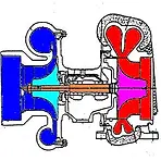
This is an exhaust gas turbine type supercharger manufactured.
Simple in construction, this device consists of an assembly of 3 cases, and a radial type turbine and acentrifugal blower built inside.
Compressed air is blown into a cooling jacket by the blower, and blow out of small holes to the back of the turbine wheel. Thus triple effects of heat insulation, turbine wheel cooling and exhaust gas sealing can be obtained.
The center case has 2 bearings which are enclosed by a bearing chamber to prevent, lubricating oil leakage.
It is further enclosed by an air chamber which is exposed to the atmosphere. There-fore, the high-pressure air leaking in small amounts during high-speed engine operation will not enter the bearing chamber.
Thus, ' the oil sump in the engine will be kept free from pressure rise.
Even when the engine is running at low speed with the blower air pressure at low level, the lubricating oil will not be contaminated by the exhaust gas.
The center case has mounting feet on the bottom. The blower case of aluminum alloy and the turbine case of heat-resistant special cast iron are installed on the center case.
The rotor shaft is supported by 2 special, floating sleeve type bearings in the bearing box.
The bearings are lubricated by the pressure oil coming from the engine through the engine lubricating oil filter.
When the lubricating oil reaches the bearings, it is recirculated via lubricating oil outlets in the center case mounting feet to the engine oil sump for reuse.
Air cooler
The air cooler is installed on the left side of the crankcase. The air which comes from the turbo blower enters the air cooler to be cooled to the required temperature before entering the cylinder head. This air cooler delivers great performance, having sufficient cooling area and high thermal efficiency as appropriate to the intended use.
Exhaust manifold
The exhaust manifold is made of cast iron. Engines with a turbo blower have dual exhaust manifolds to make effective use of the exhaust gas energy, prevent exhaust gas interference with other cylinders, and thus improve engine performance.
The exhaust manifolds have the water jackets to cool the manifolds and are connected to the turbo blower.
I learned about SHIP Turbo blower(TURBO CHARGER), Air cooler, Exhaust manifold this time.
The Diesel is designed as a high-speed, general-purpose diesel engine on the basis of our own research efforts, and has been delivered to many users both at home and abroad for its superb performance, durability, reliability and economy.
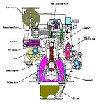
The engine is a vertical, single-acting, 4-stroke cycle diesel which is available in a series of models with or without a turbo blower.
The engine is used extensively as a marine main engine, marine auxiliary engine, factory main generator, emergency generator for buildings, and as a power plant for various industrial uses.
The engine body is a one-piece cast iron structure, which is designed to be sturdy and com-pact for high-speed operation. The engine is also designed for ease of handling, maintenance and inspection.
In addition, the engine has the following performance features.
(1) The engine is mass-produced so that the cylinder heads, cylinder liners, pistons, crankshaft, connecting rods and other major parts and valves of the same size are interchangeable.
(2) The major rotating parts of the engine are well balanced to minimize vibration and noise during engine operation. (3) The engine is direct injection type and starts easily even in the cold season.
(4) The Bosch type fuel injection pumps are simple in structure and easy to adjust.
(5) The engine is coupled as a marine auxiliary engine to a standard, single-bearing generator with a self-exciter into a compact marine generator under a technical tieup with a generator manufacturer, and is available in a series of models (CNS Series).
Engine construction
(1) Crankcase and oil pan
The crank room is formed by the cylinder column, which holds cylinder liner and the cylinder crankshaft, and the oil pan, both of which are assembled into one-piece construction. The crankshaft is held by so-called hunger type bearings in the cylinder culumn. The liner are so-called wet liners forming water jackets with the inner surface of the cylinder column to improve liner cooling.
The lower neck in the liner hole has two O-ring and square ring to separate the water jacket from the crankcase.
ON the left side of the cylinder column is the intake and exhaust valve device which is connected to the camshaft via a bearing. In rear of the crankcase is the gear case which houses various gears, and may be connected the flywheel case where necessary.
On the top of the cylinder column there are six bolts for each cylinder for tightening the cylinder heads, and also special metal parts for feeding lubricating oil and cooling water to the cylinder heads. The oilpan is bolted to the bottom of the crankcase. Made of steel plates, the oil pan has the suction pipe for the main lubricating oil pump and the suction pipe for the standby lubricating oil pump which serves also as a lubricating oil drain pipe inside. The pipe ends are fitted with a suction filter.
(2) Cylinder heads
The cylinder heads are a one-piece, single cylinder type. They are mounted with copper ring gaskets on the cylinder column by means of 6 bolts each, and form the main combustion chambers with the top of each piston. The cylinder head is provided with two intake valves and two exhaust valves, a fuel injection valve, etc.
The intake and exhaust valves are made of special heat-resistant steel, and are reinforced with a layer of stellite where they come into contact with the valve seats and rocker arms. The cylinder heads use valve seats of special-steel. and exhaust valves have valve rotators which automatically rotate the valves as the valves are opened and closed.
This provides sufficient valve durability against gas blowout.
The inside of the cylinder head is lubricated by a forced lubricating system which feeds lubricating oil through a special metal part. The cylinder head is totally enclosed inside.
A decompression plug which is used in engine turning, etc. is provided on the cylinder head side.
(3) Pistons and connecting rods
The pistons and are made of special cast iron or cast F.C.D depending on what purpose the engine will be used for. Each piston has three compression rings and one oil ring. The top compression ring is chromed and this reduces wear considerably.
The oil ring is a so-called coil expander ring having a built-in coil spring for added tension. The pistions are connected. to the connecting rods with piston pins
The connecting rods are made of especially tough steel, forged to have an I-shaped cross section. No drill hole is made in the connecting rod to maintain the durability of the crank pin metal. The small end bushing is splash lubricated by jet cooling.
The connecting rods are connected to the crankshaft at their large end. The large end, which consists of two parts, is assembled with two cap bolts.
The bearings are made of thin 3-Layer metal to assure sufficient durability against large loads. The large end is an important part, which is one of three internal engine parts that are often disassembled.
For this reason the bolts must be torqued to the specified value. As mentioned before, these cap bolts are important and will often have to be removed so that care must be exercised when disassembling and assembling the large ends of the connecting rods. The bolts are punched with match marks for location identification. The cap bolts must be replaced with new ones after a specific period of use like some other parts.
(4) Crankshaft
The crankshft is a one-piece die-forged shaft or a free-forged shaft with 8 balance weight of special steel.
The crank journals and pins are carburized and precision-finished by grinding the outside surfaces. The crankshaft is well balanced to eliminate harmful vibrations at high speed.
The crank journals carry 3-layer (kelmet-metal) thin bearings. This and the hardened journals of the crankshaft assure ample strength against great loads. The bearings are complete units so that they can be easily replaced and offer sufficient accuracy.
The output end of the crankshaft is fitted with the flywheel and starting ring gear. Where necessary, a mass plate or a silicon damper is attached to that end of the crankshaft.
(5) Gear Train
The gear train is housed in a crankcase on the output end of the engine, and drives the camshaft, fuel injection pump, lubricating oil pump and cooling water pump.
The intermediate gears for driving the camshaft, fuel injection pump, etc. must be accurately timed so that each of these gears is punched with match marks on its teeth.
All the gears are made of carefully selected materials and their teeth appropriately shaped and treated to assure ample strength at high-speed, large-load operation and to minimize noise. The gear carries various devices on the outside.
(6) Starting system
The standard starting system for this engine is an air motor starting system using com-pressed air or a electrical starting system using sell-motor.
The air motor is started by low-pressure air of 12 kg/cm2 which is fed through a quick valve to drive the vane type air motor, which drives the ring gear on the crankshaft via a pinion to start the engine.
The system has been favorably accepted by many customers for many features which include simpler construction than that of other systems and easy maintenance and inspection.
(7) Fuel control device
The fuel control device is located on the right side of crankcase. The engine can be idled or run at the rated speed. with a single handle. A fine adjustment of the rated speed can also be made easily.
Depending on customer specifications, a fine adjustment of the engine speed can be made with a motor by remote control.
The stop handle is located close to the engine speed adjusting lever. The starting handle is arranged compactly in a single place for easy handling.
(8) Fuel oil system
The fuel oil system includes filters, feed pump, fuel injection pump, fuel injection piping, nozzle holders, nozzles, etc. Two kinds of filters are used. The first filter is an auto-clean type, which removes relatively large foreign particles from the fuel oil, and can be cleaned without disassembling even when the engine is running.
The second filter (for regularly used engines only) is a wire type consisting of two filters, one of which may be opened for cleaning while the engine is running. The second filter removes fine foreign particles.
The feed pump is built inside the fuel injection pump. It is a plunger type pump driven by the camshaft which runs through the fuel injection pump. Even when the engine is not running, the plunger can be manually moved for making various kinds of checks on the fuel oil system.
(9) Fuel injection pump, nozzles and governor
The fuel injection pump is a Boech 6-cylinder one-piece type, to which the governor and feed pump are directly connected.
The fuel injection pump is installed on the right side of the engine ) as viewed from the front of the engine), and driven from the the plungers in the firing order of the cylinders to generate high-pressure fuel oil. Fuel oil quantity can be uniformly changed automatically by turning the plungers with the rack.
A fuel injection valve is of automatic type and has such a construction as possible to be adjusted to the specified injection pressure with a spring, providing the best injection of fuel and perfect combustion is assured with whatever load you may operate the engine.
The governor is a centrifugal governor which is directly mounted on the fuel injection pump, and has a control lever for engine speed control and a stop lever for stopping the engine.. The governor shaft, whose speed is increased by a gear on the camshaft of the fuel injection pump, has governor weights; the rack is automatically adjusted by the balance between governor springs and the centrifugal force of the governor weights to maintain uniform engine speed.
(10) Lubricating oil system
The lubricating oil in the oil pan is pumped up by the main lubricating oil pump via the strainer in the oil pan, running through the oil cooler and lubricating oil filter into the main pipe, which is cast into the crankcase, to lubricate various parts of the engine, and then returning to the oil pan. It is a forced lubricating system.
The internal working parts have drilled holes for letting the lubricating oil flow. The lubricating oil pump is a gear pump which is mounted to the gear case and driven by the drive gear.
The discharged lubricating oil is regulated to the correct pressure by the pressure regulating valve mounted on the blaket for the lubricating oil filter. The lubricating oil filter is a twin, notch-wire type. Installed on the right side of the crankcase. any one of the twin filters can be removed for cleaning by turning the changeover-cock-even when the engine is running. The lubricating oil cooler (shell tube type) has excellent cooling performance.
(11) Cooling water system
Cooling water pump The cooling water system is the fresh water secondary cooling system. The cooling water pump is directly mounted to the gear case and is driven with a gear.
The fresh water pump is a centrifugal pump Oil seals are used for preventing oil leakage. Mechanical seals are used for completely preventing water leakage and for preventing damage to the shaft. The fresh water discharged out of the fresh water pump enters the crankcase and flow through the cylinder jacket, cylinder head and water-cooled exhaust pipes before entry to the fresh water cooler. The fresh water then passes through the passage in the crankcase and is led to the fresh water pump.
• Seawater pump
A Wesco pump is used. This pump is divided into a vacuum chamber and a pressure chamber, and pressure chamber is equipped with an external casing which also functions as an air-water separation chamber. When the engine is started with priming sufficiently made through the external casing, water containing air bubbles is fed to the separation chamber from the pump casing because of revolution of the impeller. The air is discharged to the exterior of the pump barrel from the separation chamber and water only is delivered to the impeller from the separation chamber. This cycle is repeated and the automatic exhaust valve or the delivery port and pumping is finally performed. Even when running of the pump is suspended, water that is required for the self-priming action for the next running will remain in the casing. At the next time and subsequent. Therefore, the pump operates in a manner that is equal to that of a usual centrifugal pump.
Fresh water cooler
The fresh water cooler is located on the rear face of the crankcase.
The fresh water cooler is of tube type and incorporates an expansion tank chamber in the upeer part and a thermostat on a side face. The topmost part of the fresh water cooler is equipped with a pressure control valve (also used as the cap for replenishment of fresh water) and the fresh water temperature is controlled in the range of 65~76℃ by means of the thermostat. Be sure to check the fresh water level by observing the water level gauge or with the pressure control valve cap removed before start of operation. If the water level is low, replenish fresh water up to the level of the cap seal. The side cover contains zinc for corrosion protection. Inspect it from time to time. Draining of the fresh water will be smooth if that cap is removed. When the fresh water is drained while it is hot, steam may jet out when the pressure control valve cap is removed. Cover up the filler port with rag or other suitable means in such a case.
I am a Korean. Please understand even if I am not good at English.
As I am interested in korea ship engines and korea car engines, I would like to share the information I know about diesel engines. I am currently working on ship engines, and I have over 10 years of experience in handling and managing many engines, including mid- and low-speed diesel and YANMAR, NIIGATA, DAIHATSU, HANSHIN, AKASAKA, B&W, but I am still studying and working on it. The goal is to share information first and secondly to learn my knowledge over and over again. The structure of the automotive diesel engine and the ship engine is similar to the basic frame, but there are many mistakes, so please refer to them.
Today, the trend toward the complexity of automobile structures, the sophistication of performance, especially electronics, is becoming even stronger. In addition, pollution (fine dust) of cars, such as emissions and noise, has become a major social issue, and his repair and safe operation have become important tasks directly related to social welfare. To improve and average the quality of education at schools and training centers and other educational institutions that train engine maintenance technologies, we are conducting various studies, but we are sharing information directly because of the lack of information.
I would like to learn more about the difference between gasoline-powered diesel engines and diesel engines. In particular, I would like to explain it to you only in terms of structure.
Basically, it's easy for you to understand if you're building or servicing an engine, but for those of you who don't have access to it, it's going to be a lot. If you understand the following, I think you're right to read my posts.
INSTRUCTION MANUAL HEAVY DISEL ENGINES!!
This manual provides general instructions for the This is an example of a diesel engine..
This instructions given herein cover all phases of the a diesel engine ranging from operation to maintenance. The instruction manual contains parts which are applicable to all types of the a diesel engine and SOME which concern specific types.
Observe those instructions which are applicable only to your engine, and read the other instructions just for reference.
Read not only those parts which consern your engine but also the other parts of the manual, which, we believe, will prove helpful in your future plans.
The manual has been compiled as mentioned below for your easy reference.
• The table of contents is divided into a Rain table of contents and sectional tables of contents which include lists of attached drawings and tables.
• Applicable models are listed at the head of paragraph.
W A R N I N G READ THIS ENTIRE MANUAL AND ALL OTHER PUBLICATIONS PERTAINING TO THE WORK TO BE PERFORMED BEFORE INSTALLING, OPERATING OR SERVICING THIS EQUIPMENT. PRACTICE ALL PLANT AND SAFETY INSTRUCTIONS AND PRECAUTIONS. FAILURE TO FOLLOW INSTRUCTIONS CAN CAUSE PERSONAL INJURY AND/OR PROPERTY DAMAGE.
1. INTRODUCTION
This manual describes the construction of Niigata Diesel Engines and the methods for their operation, handling and maintenance.
However, the manual does not necessarily cover the details of all the problems which might come up during the use of your engine. It is hoped, therefore, that the engine operator acquires a full knowledge of the instructions given in this manual, pays attention to the condition of the engine at all times, and keeps studying the engine so that he will be able to take quick and appropriate steps against what might develop with the engine.
Daily inspection and maintenance will enable the engine operator to detect trouble symptoms and prevent accidents, and thus prolong the engine life and keep the engine in satisfactory condition for years to come.
Dimensions, Screws, Engine Name Plate The materials and accessories used for the engine are manufactured mainly in Japan, and meet the specifications of the International Standardization Organization (ISO), Japanese Industrial Standard (JIS).
As a marine engine, it has passed the various tests and checks specified by the following Registers of Shipping, and qualifications therefore can be obtained: (NK)., (LR)., (AB). and others The metric system was applied in the design and manufacture of the engine.
Here's what I'm going to tell you.
Models and Factory, Fuel oil, Fuel oil properties, Factory, Lubricating oil, Specifications, Cooling water, Engine specifications, Quantities of lubricating oil, Specifications of accessories and cooling water, and auxi1 iaries, Engine Installation, Site Condition, Foundation work (for land engines), Operation of the Diesel, Engine installation and alignment, Outline of Construction, Engine lifting, General, Caution in rigging, Engine construction, Fuel Oil, Lubricating Oil and Cooling Water
Besides
Operation principle, Engine timing chart, General view, Cylinder head, Piston and connecting rod, Gear case, Air motor starting system, Cooling water pump, Turbo blower, Lubricating oil quantity, Engine lifting method, Fuel oil gravity tank, Expansion joint and exhaust manifold, installing method, Engine room ventilation method, Output correction, Light oil specifications, Heavy oil specifications, Kerosene specifications, Recommended brands of lubricating oil, Limits of cooling water properties.
Of course, there may be some omission here, but I will do my best to inform you of the information.
GENERAL Site Conditions
The engine outputs mentioned in this manual apply under the following standard conditions.
The output of an engine is subject to change depending on the site conditions where the engine is installed. It is suggested that, when selecting an engine output, you inform us of your site conditions and then determine an appropriate engine output. Attention must be paid to any change in site conditions so that the engine will not be overloaded when operating it on a load.
Standard conditions (for the engines specified in this manual)
Altitude (above sea level) From 0 up to 300m (Atmospheric pressure 760mmHg)
Engine ambient temperature 40℃
Cooling water inlet temperature
Marine engines 32℃
Land engines 35℃
There are various mathematical formulas for calculating the percentage of output decrease due to the effect of site conditions, but the following ISO (International Standardization Organization) output correcting tables are used for obtaining the percentage of output decrease for the engines.
Operation of the this Diesel
The this Diesel is a 4-stroke cycle diesel engine. The 4-stroke cycle diesel engine has four strokes - suction, compression, expansion and exhaust.It is a so called compression ignition engine which injects fuel into compressed air for spontaneous ignition.
(1) Suction stroke
The exhaust valve is closed, and the piston goes down while the intake valve is opened to let air into the cylinder through the intake valve.
(2) Compression stroke
The intake and exhaust valves are closed and the piston goes up so that the air inside the cylinder is compressed into high-temperature air.
(3) Expansion stroke
When the piston reaches the top dead center, the fuel is injected in fine particles into the combustion chamber by the fuel injection valve nozzle, ignites itself and burns as it is exposed to the high-temperature air. The resultant high-pressure gas pushes the piston downward to rotate the crankshaft.
(4) Exhaust stroke
As the piston reaches the bottom dead center after the expansion stroke, the exhaust valve is opened to let the exhaust gas out so that the pressure inside the cylinder decreases. As the this Diesel piston rises again, the remaining exhaust gas is forced out of the cylinder. Then the suction stroke begins again.
Each cylinder completes these four strokes while the crankshaft turns twice. This process is repeated to cause the engine to run.
The posting looked at diesel's four-stroke cycle. Remember, there are four strokes: suction, compression, expansion, and exhaust.We looked at the intake air temperature of the land engine versus the intake air temperature of the ocean engine. The posting looked at diesel's four-stroke cycle. Remember, there are four strokes: suction, compression, expansion, and exhaust.
Again, I hope you understand even if you are not good at English. Thank you for reading.
기계가공 용어 기계 용어 사전 기계공학 용어사전 가공 기호 등등 여러 단어가 중복으로 포함이 되어 있어서, 생산 직무 엔지니어에게는 도움이 될 것이고, 어느 생산 직무 엔지니어에게는 도움이 안 되는 단어도 포함이 되어 있을 것입니다. 필요한 단어, 용어만 찾으시면 될 거 같습니다. 저는 무에서 유를 창조하는 엔지니어 님들이 아티스트라고 생각합니다. 최고의 에이스 아티스트입니다. 그럼 많은 도움이 되시길 바랍니다. 이번 단어는 T에서 Z까지 준비되어 있습니다. 아래 참고 부탁드립니다.
제작 용어, 기계 단어, cnc mct 밀링 단어 등 기계나 제작을 하는데 토털 적으로 필요한 용어와 단어들을 수집한 자료입니다. 어떤 기술자에게는 필요 없는 단어 일수도 있고, 반대로 도움이 되는 교육 자료일 수도 있습니다. 기계를 다루면서 도움이 되었으면 합니다. 아래 단어들은 알파벳순으로 나열이 되어있습니다. 더 필요한 자료가 있으시면 언제든지 요청해주시면 최대한 도움을 드리도록 하겠습니다.
저도 엔지니어이지만 용어를 모르면 많은 곤욕을 치르곤 합니다. 작업 시 그래도 도움이 되는 용어들을 모아봤습니다. 이번 시간에는 F~M까지 알파벳으로 시작하는 단어, 용어들을 모아봤습니다. 많은 엔지니어께서 개발, 가공, 제작, 생산, 설치하시는데 보탬이 되었으면 좋겠습니다. 저도 10년 차이지만 아직 많이 모르는 단어가 많습니다. 기계에 대해 지식과 경험이 있는 자동차 엔지니어, 기계 엔지니어, 비행기 엔지니어, 선박 엔지니어, 자동화 엔지니어 등 자기가 맡은 분야에 전문가가 되어 진정한 엔지니어가 되시기 바랍니다.